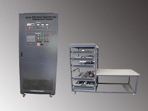
Model: DLWD-DJ22-III
Overview of the motor and electrical technology comprehensive training device
This device is one of Dolang’s pieces of comprehensive training equipment that utilizes different hanging boards according to the end user’s various training requirements. The device is applicable across a wide range of training lessons. The front and back side allow two students to work on the device simultaneously. The independent power supplies allow for isolating the two sides and facilitates individual expansion and upgrading as needed.
The comprehensive training device is equipped with a variety of motors as controls and enables students to learn a variety of motor motion controls, operating characteristics and mechanical properties, which is conducive to studying and troubleshooting the motor.
Technical parameter of the motor and electrical technology comprehensive training device
Input power: three-phase, five-wire AC 380V±10% 50Hz/60Hz
Capacity : < 1KVA
Total dimension : 1930×1170×710mm
Optional components
Teaching resourcesSimulation software
Siemens PLC and frequency converter Mitsubishi PLC and frequency converter
Completed teaching programs:
(I) DC motor experiment
1. DC series motor experiments
2. DC series motor operating characteristics, mechanical properties
3. DC series motor speed control experiments start
4. DC-excited motor experiments
5. DC separately excited motor operating characteristics, mechanical properties
6. DC separately excited motor speed control and reverse start experiment
7. DC shunt motor experiments
8. DC shunt motor operating characteristics, mechanical properties
9. DC shunt motor starting control experimental.
(II) Asynchronous motor experiment
1. Mechanical properties of three-phase squirrel cage induction motor measurement
2. Three-phase asynchronous motor starting and speed regulation experiment
3. Measurement of mechanical properties of three-phase double speed motor
4. Three-phase double-speed motor starting and speed regulation experiment
5. Measurement of mechanical properties of single-phase capacitor start motor
6. Single-phase capacitor start motor starting and speed regulation experiment
(III) Electric Traction control relay contacts
1.Forward control circuit of motor ①Point forward control circuit
Contactor self-locking forward control circuit
Contactor with overload protection self-locking control circuit forward
Point and continuous mixing forward control circuit
2. Reversible of three-phase asynchronous motor control circuit
Inverted switch reversing control circuit
Reversible control line of contactor interlock
Reversible control circuit of button interlock
Reversing control circuit of button, contactor dual interlocking
Position control circuit (Also known as the stroke control or limit control circuit)
Sequence control circuit
More control circuit
3. Step-down starting of three-phase asynchronous motor control line
The stator winding resistance concatenated step-down starting control circuit
Manual control -△Step-down starting line
Button, contactor control -△Step-down starting control circuit
Time relay automatic control -△Step-down starting line
Rotor series three-phase resistance starting control circuit
Button action series resistance starting control circuit
Time relay automatic control circuit
Wound rotor asynchronous motor CAM controller circuit
4. Three-phase asynchronous motor brake control circuit
Reverse connect braking control circuit (Unidirectional and bidirectional)
Energy consumption braking control circuit(No transformer type and with transformer type)
5. Double speed asynchronous motor control line
Contactor control two-speed motor control circuit
Time relay control two-speed motor control circuit
6. Basic control circuit of shunt/series/separately excited/compound DC motor
Manual/automatic starting control circuit
Reversing control circuit
Brake control circuit(Energy consumption braking, reverse connect braking)
Speed control circuit(The armature loop series resistance, change the main magnetic flux, the armature voltage)
(IIV) Speed adjustment by transducer
1) Frequency converter basic operation training
2) Frequency converter speed regulation practice
3) Open loop speed control system of frequency converter based on the PLC communication mode
4) Closed-loop speed control of frequency converter based on the PLC communication
(IIV) PLC
1) Basic instruction practice
2) Design and debug three-phase asynchronous motor Y / △ start control circuit by the use of PLC
3) Design and debug three-phase asynchronous motor reverse control circuit by the use of PLC
(VI) Micro motor experiment
1) Control and use of AC servo motors
2) Pulse control AC servo motor training by PLC
3) The control and use of stepper motor
4) The pulse control stepper motor training by PLC.