Model: DLWD-DGJS13
Overview of the electronic and electric drive training system
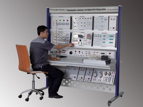
This system is designed for training with and studying analog and digital electronics, circuit principles and motor drag experiments. The training system consists of two parts, a workbench (including the power control panel) and experimental modules.
Technical parameter of the electronic and electric drive training system
Input power : three-phase, five-wire 380V±10% 50Hz/60Hz
Output power : AC 0~450V , AC 380V , AC 220V , DC 1.25 ~30V Two-way adjustable DC power supply,
DC 0 ~ 500mA Adjustable constant current source , AC 0~ 30V safety terminal output
Working environment : temperature -10℃ ~ +40℃ , relative humidity <85% (25℃ ) , Altitude <4000m
Capacity : < 1.5kVA
Motor power : < 180W
Wireless power control distance : > 50m (Optional functions)
Total dimension : 1670×800×1750mm
Optional components
Oscilloscope
Multimeter
Signal source
Training Content:
Electrotechnic experiments
1. Basic electrotechnics instrumentation use and measurement error calculation
2. How to reduce instrument measurement error
3. Mapping of linear and nonlinear circuit elements voltage characteristics
4. The measurement of potential, voltage and drawing of circuit, potential
5. Kirchhoff's law verification
6. Superposition theorem verification
7. Equivalent transferring of voltage source and current source
8. Thevenin theorem verification
9. Norton Theorem verification
10. Dual-port network test
11. The experiment researching of controlled source VCCS, VCVS, CCVS, CCCS
12. The observation and measurement of typical electrical signal
13. RC first order circuit response test
14. Second order dynamic circuits response test
15. R, L, C component impedance characteristic test
16. R C series and parallel connection frequency selective network characteristic test
17. R, L, C series connection resonant circuit research
18. Measure AC circuit equivalent parameters with Three-meter method
19. Study sinusoidal steady AC circuit phasor (fluorescent power factor improvement experiments)
20. Mutual inductance circuit experiment
21. The testing of single-phase core transformer features
22. Three-phase AC circuit voltage, current measuring
23. Three-phase circuit power measurement
24. Single-phase walt hour meter calibration
25. Negative impedance converter and application
26. Gyrator and application
27. Power traction experiment:
28. Direct start controlling of three-phase asynchronous motor
29. Three-phase asynchronous motor contactor inching control circuit
30. Three-phase asynchronous motor contactor self-locking control circuit
31. Y- △ start automatic control circuit
32. Three-phase asynchronous motor contactor with button interlocking reversing control circuit
33. Three-phase asynchronous motor energy consumption braking control circuit
34. Without transformer half-wave rectification circuit energy consumption braking control circuit
35. With transformer full-wave rectification energy consumption braking control circuit
36. Sequence control of three phase asynchronous motor
37. Multi control of three phase asynchronous motor
38. Simulate the workbench auto back and forward control circuit
39. Electronic Experiment:
40. Amplifying circuit
41. Negative feedback amplifying circuit
42. Emitter follower
43. Common emitter amplifier circuit
44. Common collector amplifier circuit
45. Common base amplifier
46. Complementary symmetry power amplifier
47. The basic parameters test of the integrated operational amplifier
48. Integrated addition circuits
49. Integrated subtract circuits
50. Integrated integral circuits
51. Integrated differential circuit
52. Proportion summation circuit
53. Integrated op-amp first-order active filter
54. Voltage comparator research
55. Waveform generating circuits
56. Active Filter
57. Integrated power amplifier
58. Integrated circuit RC sinusoidal oscillator
59. Rectifier filtering and regulator circuit
60. Series regulator circuit
61. Integrated regulator
62. Waveform conversion circuit
63. Transistor switching characteristics, the limiter and clamper
64. Logic functions and parameters test of the TTL integrated logic gates
65. The logic functions and parameters test of CMOS integrated logic gate
66. Combinational logic circuit
67. Trigger
68. Sequential Circuits Testing and Research
69. Utilize gates circuits to generate a pulse signal
70. 555 time-base circuit